Introduction
A flame sensor module performs detection by capturing infrared wavelengths from flame. It can be used to detect and warn of flames. In this experiment, we use the sensor to make a flame alarm.
Components
– 1 * SunFounder Uno board
– 1 * USB data cable
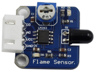
– 1 * Flame sensor module
– 1 * Passive buzzer module
– 1 * 4-Pin anti-reverse cable
– 1 * 3-Pin anti-reverse cable
– 1 * Jump wire (F to F)
Experimental Principle
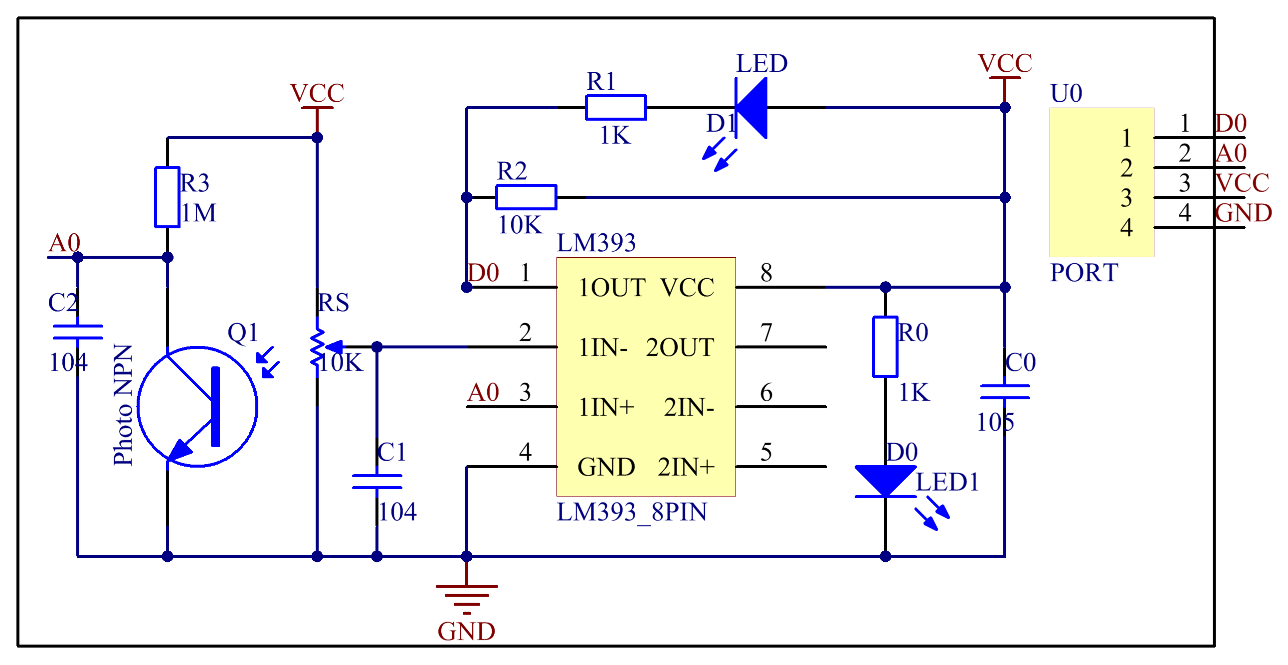
There are several types of flame sensors. In this experiment, we will use a far-infrared flame sensor. It can detect infrared light with a wavelength ranging from 700nm to 1000nm. A far-infrared flame probe converts the strength changes of the external infrared light into current changes. And then it converts analog quantities into digital ones.
In this experiment, connect pin D0 to the digital port 8 of the SunFounder board. Then when the flame sensor detects flame signals, the buzzer beeps and the corresponding LED lights up. When it detects no flame signals, the buzzer stops and the LED goes out.
The schematic diagram of the module is as follows:
Experimental Procedures
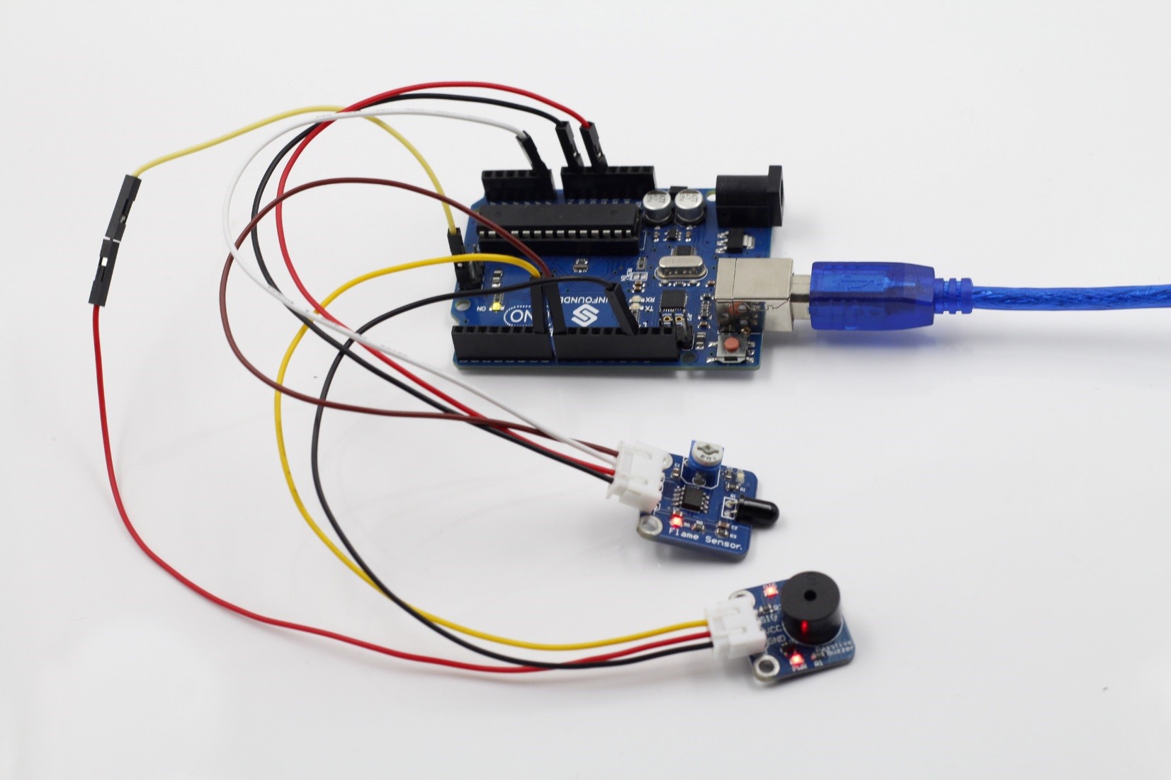
Step 1: Build the circuit
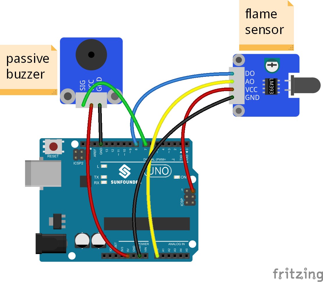
The wiring between the flame sensor and SunFounder Uno board:
| Flame Sensor | SunFounder Uno |
| D0 | 8 |
| A0 | A0 |
| VCC | 5V |
| GND | GND |
The wiring between the passive buzzer and SunFounder Uno board:
| Passive Buzzer | SunFounder Uno |
| SIG | 7 |
| VCC | 5V |
| GND | GND |
Step 2: Program (Please refer to the example code in LEARN -> Get Tutorials on our website)
Step 3: Compile the code
Step 4: Upload the sketch to the SunFounder Uno board
Now, ignite a lighter near the flame sensor. Then the buzzer will beep, and the LED on the flame sensor module and that attached to pin 13 of the SunFounder board will light up.
Code
| /*********************************************** * name:Flame Alarm * function:ignite a lighter near the flame sensor. * Then the buzzer will beep, * and the LED on the flame sensor module and that attached to pin 13 of the SunFounder board will light up. * connection: * flame sensor module SunFounder Uno R3 * D0 8 * A0 A0 * VCC 5V * GND GND * Buzzer Module SunFounder Uno R3 * SIG 7 * VCC 5V * GND GND ***************************************************/const int analogInPin = A0;// A0 attach to A0 const int digitalInPin = 8; //D0 attach to digital 8 const int ledPin = 13; //pin13 built-in led const int buzzerPin=7; //buzzer attach to digital 7void setup() { //set the pins state pinMode(digitalInPin,INPUT); pinMode(ledPin,OUTPUT); pinMode(buzzerPin,OUTPUT); Serial.begin(9600);//initialize serial }void loop() { int analogVal = analogRead(analogInPin); //read the value of A0 Serial.print(“A0: “); Serial.println(analogVal);//print to serial monitor boolean stat = digitalRead(digitalInPin); Serial.print(“D0: “); Serial.println(stat); // print to serial monitor Serial.println(” “); if(stat == HIGH) { digitalWrite(ledPin,LOW); noTone(7);//if you want to play different pitches on multiple pins, you need to call noTone() on one pin before calling tone() on the next pin. } if(stat == LOW) { digitalWrite(ledPin,HIGH); tone(7,320,200);//in pin7 generate a tone ,it’s frequency is 320hz and the duration of the tone is 500 milliseconds } delay(500); // used to slow down readings while calibrating } |