Introduction
Based on the Hall Effect, a hall sensor is one that varies its output voltage in response to a magnetic field. Hall sensors are used for proximity switching, positioning, speed detection, and current sensing applications.
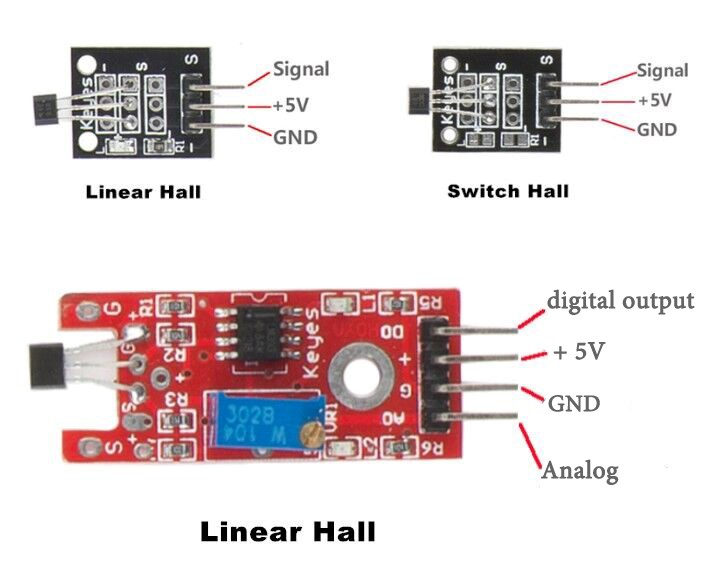
Hall sensors can be categorized into linear (analog) Hall sensors and switch Hall sensors. A switch Hall sensor consists of voltage regulator, Hall element, differential amplifier, Schmitt trigger, and output terminal and it outputs digital values. A linear Hall sensor consists of a Hall element, linear amplifier, and emitter follower and it outputs analog values.
There are three types of hall sensor module in this kit (as shown below): linear Hall sensor (in two forms) which outputs analog signals, and switch Hall sensor which outputs digital signals. If you add a comparator to the linear Hall sensor, it will be able to output both analog and digital signals.
Components
– 1 * SunFounder Uno board
– 1 * USB data cable
– 1 * Hall sensor module
– 1 * LCD1602
– 1 * Potentiometer
– Several jumper wires
Experimental Principles
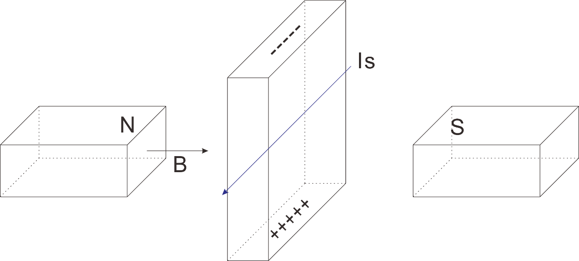
Hall Effect
Hall Effect is a kind of electromagnetic effect. It was discovered by Edwin Hall in 1879 when he was researching conductive mechanism about metals. The effect is seen when a conductor is passed through a uniform magnetic field. The natural electron drift of the charge carriers causes the magnetic field to apply a Lorentz force (the force exerted on a charged particle in an electromagnetic field) to these charge carriers. The result is what is seen as a charge separation, with a buildup of either positive or negative charges on the bottom or on the top of the plate.
Hall Sensor
A hall sensor is a kind of magnetic field sensor based on the effect.
Electricity carried through a conductor will produce a magnetic field that varies with current, and a Hall sensor can be used to measure the current without interrupting the circuit. Typically, the sensor is integrated with a wound core or permanent magnet that surrounds the conductor to be measured.
Experimental Procedures
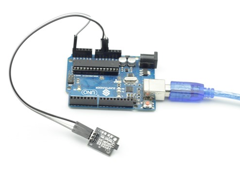
For linear Hall sensor module, please take the following steps.
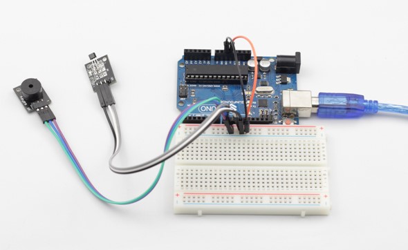
Step 1: Build the circuit
Linear Hall Sensor Module SunFounder Uno
S —————————————- A5
– —————————————- GND
+ —————————————– 5V
Step 2: Program (Please refer to the example code in LEARN -> Get Tutorial on our website)
C Code
| int sensorPin = A5; // select the input pin for the potentiometer int ledPin = 13; // select the pin for the LED int sensorValue = 0; // variable to store the value coming from the sensorvoid setup() { pinMode(ledPin, OUTPUT); Serial.begin(9600); }void loop() { sensorValue = analogRead(sensorPin); digitalWrite(ledPin, HIGH); delay(sensorValue); digitalWrite(ledPin, LOW); delay(sensorValue); Serial.println(sensorValue, DEC); } |
Step 3: Compile
Step 4: Upload the sketch to SunFounder Uno
Now, you can see the LED attached to pin 13 on SunFounder Uno board blinking. If a magnet approaches the linear Hall sensor, the blinking frequency of LED will increase or decrease.
For Switch Hall Sensor module
Step 1: Build the circuit
Switch Hall Sensor Module SunFounder Uno
S —————————————-Digital 8
– —————————————- GND
+ ———————- —————– 5V
Step 2: Program (Please refer to the example code in LEARN -> Get Tutorial on our website)
C Code
| const int hallPin = 8; //the pin of hall sensor attach to const int ledPin = 13; //the number of the led int val = 0; //the variable to store the value read from hall sensor /********************************/ void setup() { pinMode(hallPin,INPUT); //initialize the hall as an input pinMode(ledPin,OUTPUT); //initialize the led as an output } /**********************************/ void loop() { val = digitalRead(hallPin); //read the value from hall sensor if(val == HIGH) { digitalWrite(ledPin,LOW); noTone(7); } if(val == LOW) { digitalWrite(ledPin,HIGH); tone(7,320,500); } } /*************************************/ |
Step 3: Compile
Step 4: Upload the sketch to SunFounder Uno
Now, place a magnet close to the switch Hall sensor. Then the indicator LED on the switch Hall sensor will light up and the buzzer will beep. At the same time, the LED attached to pin 13 on the SunFounder Uno board will light up.
For linear Hall sensor module (with a comparator added)
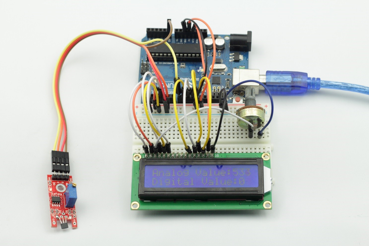
Step 1: Build the circuit
Linear Hall Sensor Module SunFounder Uno
AO ——————————————- A0
DO ——————————————- Digital 8
– ——————————————– GND
+ ———————————————- 5V
LCD1602 connection: connect pin RS to digital pin 3; R/W to GND; E to digital pin 4; D4~D7 to digital pin 9 to 12; VSS to GND; VDD to 5V; A to 3.3V; K to GND
Potentiometer connection: Connect its middle pin to VO of LCD1602 and any other pin to GND
Step 2: Program (Please refer to the example code in LEARN -> Get Tutorial on our website)
C Code
| #includeconst int ledPin = 13; const int A0Pin = A0; #define D0Pin 8 // initialize the library with the numbers of the interface pins LiquidCrystal lcd(3, 4, 9, 10, 11, 12);void setup() { pinMode(ledPin,OUTPUT); pinMode(D0Pin, INPUT); lcd.begin(16, 2); // set up the LCD’s number of columns and rows: }void loop() { int analogVal = analogRead(A0Pin); int digitalVal = digitalRead(D0Pin); lcd.setCursor(0,0); lcd.print(“Analog Value:”); lcd.print(analogVal); lcd.setCursor(0,1); lcd.print(“Digital Value:”); lcd.print(digitalVal); } |
Step 3: Compile
Step 4: Upload the sketch to SunFounder Uno
Now, put a magnet close to the linear Hall sensor, and the indicator LED on the linear Hall sensor will light up. At the same time, the analog and digital value displayed on the LCD will change accordingly.