Introduction
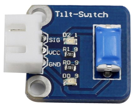
The tilt switch sensor module is a ball tilt switch with a metal ball inside. It is used to detect inclinations of a small angle.
Components
– 1 * SunFounder Uno board
– 1 * USB data cable
– 1 * Tilt switch module
– 1 * 3-Pin anti-reverse cable
Experimental Principle
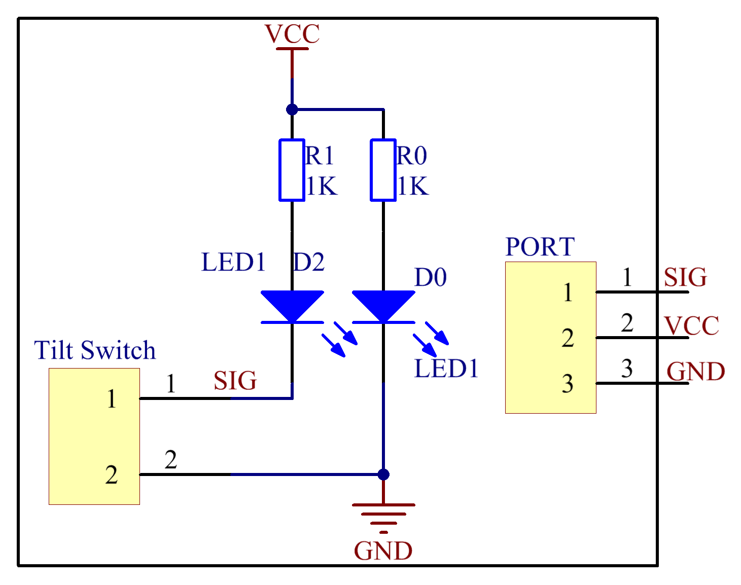
Apply the principle that the ball in the switch moves with different angles of inclination to make triggering circuits. The tilt switch module uses a ball tilt switch with bidirectional conduction. When it tilts towards either side, as long as the tilt degree and force meet the condition, the switch will be energized; thus, it will output low level signals.
In this experiment, we use a tilt switch module and an LED that has been attached to pin 13 of the SunFounder board to build a simple circuit.
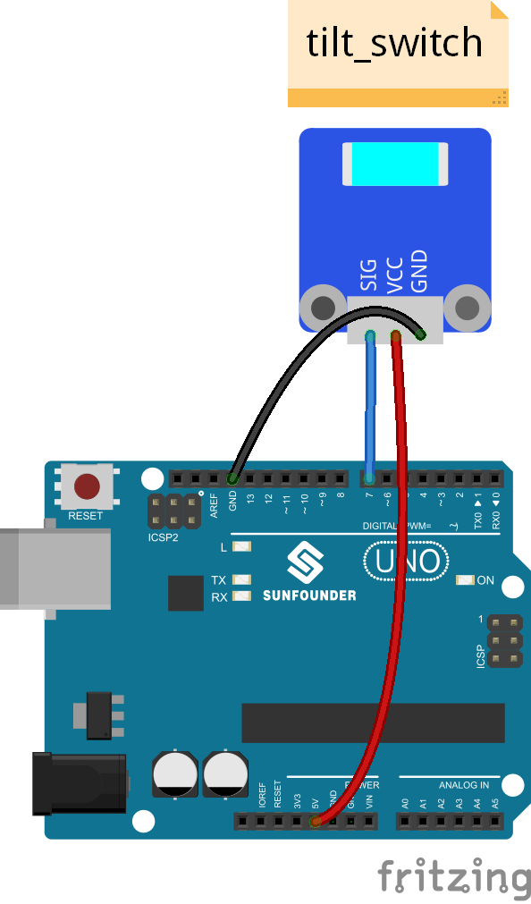
With the LED attached to pin 13, connect pin SIG to digital pin 7 of the SunFounder Uno board. Then the tilt switch outputs low signals and the LED will be on. Otherwise it will be off.
Experimental Procedures
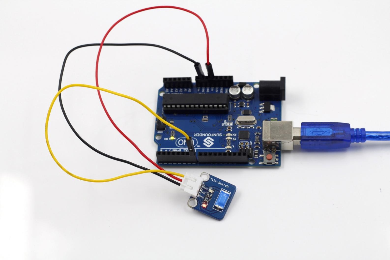
Step 1: Build the circuit
Step 2: Program (Please refer to the example code in LEARN -> Get Tutorial on our website)
Step 3: Compile
Step 4: Upload the sketch to SunFounder Uno board
Now, tilt the switch and the LED attached to pin 13 on SunFounder Uno board will light up.
Code
| const int sigPin = 7; // the number of the tilt switch pin const int ledPin = 13; // the number of the LED pin// variables will change: boolean sigState = 0; // variable for reading the tilt switch statusvoid setup(){ // initialize the LED pin as an output: pinMode(ledPin, OUTPUT); // initialize the tilt switch pin as an input: pinMode(sigPin, INPUT); }void loop(){ // read the state of the tilt switch value: sigState = digitalRead(sigPin); if (sigState == HIGH) { // turn LED on: digitalWrite(ledPin, LOW); } else { // turn LED off: digitalWrite(ledPin, HIGH); } } |