Introduction
Based on Hall Effect, a Hall sensor is a one that varies its output voltage in response to a magnetic field. Hall sensors are used for proximity switching, positioning, speed detection, and current sensing applications.
Hall sensors can be categorized into linear (analog) Hall sensors and switch Hall sensors. A switch Hall sensor consists of voltage regulator, Hall element, differential amplifier, Schmitt trigger, and output terminal and it outputs digital values. A linear Hall sensor consists of Hall element, linear amplifier, and emitter follower and it outputs analog values. If you add a comparator to a linear (analog) Hall sensor it will be able to output both analog and digital signals.
Required Components
– 1 * Raspberry Pi
– 1 * Breadboard
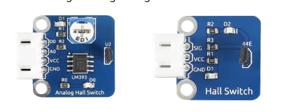
– 1 * Analog Hall Switch module
– 1 * Dual-color LED module
– 1 * Switch hall module
– 1 * PCF8591
– 2 * 3-Pin anti-reverse cable
– 1 * 4-Pin anti-reverse cable
– Several Jumper wires
Experimental Principles
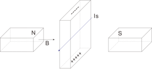
Hall Effect
Hall Effect is a kind of electromagnetic effect. It was discovered by Edwin Hall in 1879 when he was researching conductive mechanism about metals. The effect is seen when a conductor is passed through a uniform magnetic field. The natural electron drift of the charge carriers causes the magnetic field to apply a Lorentz force (the force exerted on a charged particle in an electromagnetic field) to these charge carriers. The result is what is seen as a charge separation, with a buildup of either positive or negative charges on the bottom or on the top of the plate.
Hall sensor
A Hall sensor is a kind of magnetic field sensor based on it.
Electricity carried through a conductor will produce a magnetic field that varies with current, and a Hall sensor can be used to measure the current without interrupting the circuit. Typically, the sensor is integrated with a wound core or permanent magnet that surrounds the conductor to be measured.
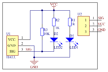
The schematic diagram of the analog Hall sensor module:
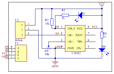
The schematic diagram of the Switch hall module:
Experimental Procedures
For switch Hall sensor, take the following steps.
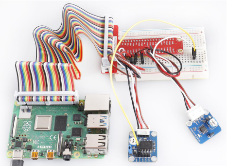
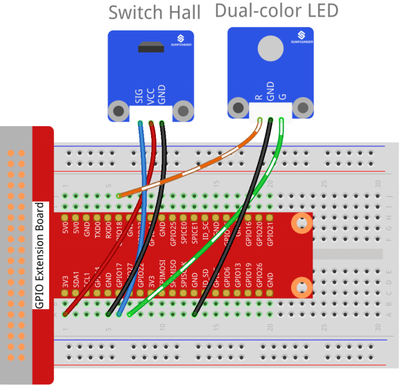
Step 1: Build the circuit.
| Raspberry Pi | GPIO Extension Board | Switch Hall Module |
| GPIO0 | GPIO17 | SIG |
| 3.3V | 3V3 | VCC |
| GND | GND | GND |
| Raspberry Pi | GPIO Extension Board | Dual-color LED Module |
| GPIO1 | GPIO18 | R |
| GND | GND | GND |
| GPIO2 | GPIO27 | G |
For C Users:
Step 2: Change directory.
cd /home/pi/SunFounder_SensorKit_for_RPi2/C/17_switch_hall/Step 3: Compile.
gcc switch_hall.c -lwiringPiStep 4: Run.
sudo ./a.outFor Python Users:
Step 2: Change directory.
cd /home/pi/SunFounder_SensorKit_for_RPi2/Python/Step 3: Run.
sudo python3 17_switch_hall.pyPut a magnet close to the Switch Hall sensor. Then a string “Detected magnetic materials” will be printed on the screen and the LED will light up.

For Analog Hall Switch, take the following steps.
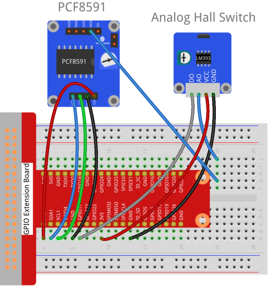
Step 1: Build the circuit.
| Raspberry Pi | GPIO Extension Board | PCF8591 module |
| SDA | SDA1 | SDA |
| SCL | SCL1 | SCL |
| 3.3V | 3V3 | VCC |
| GND | GND | GND |
| Analog Hall Switch | GPIO Extension Board | PCF8591 module |
| DO | GPIO17 | * |
| AO | * | AIN0 |
| VCC | 3V3 | VCC |
| GND | GND | GND |
For C Users:
Step 2: Change directory.
cd /home/pi/SunFounder_SensorKit_for_RPi2/C/17_analog_hall_switch/Step 3: Compile.
gcc analog_hall_switch.c -lwiringPiStep 4: Run.
sudo ./a.out For Python Users:
Step 2: Change directory.
cd /home/pi/SunFounder_SensorKit_for_RPi2/Python/Step 3: Run.
sudo python3 17_analog_hall_switch.pyNow “Current intensity of magnetic field : xxx ” will be displayed on the screen. Put the magnet close to the analog Hall sensor, with the north magnetic pole towards the sensor, and then ” Magnet: North.” will be displayed. Move the magnet away, and ” Magnet: None.” will be printed. If the magnet approaches the sensor with the south magnetic pole towards it, ” Magnet: South.” will be printed on the screen.
Note: Pin D0 of the Analog Hall Sensor will output “0” only when the south pole of the magnet approaches it, otherwise it will output “1”.